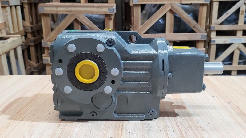
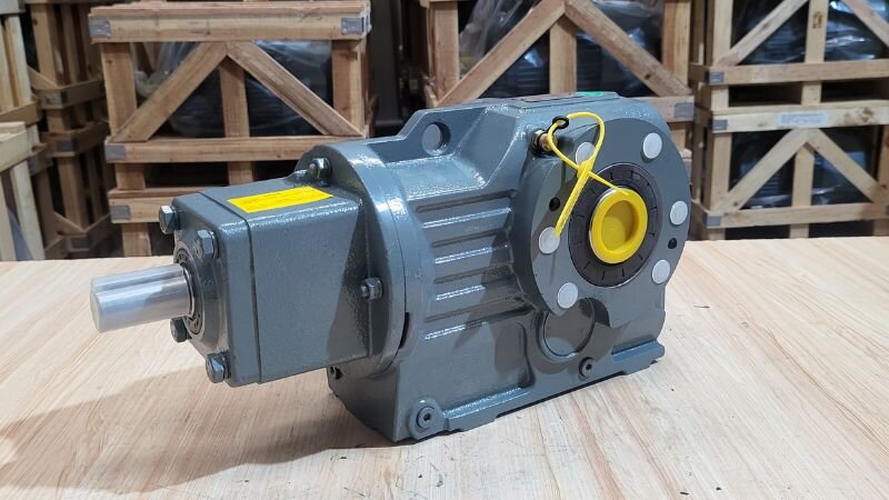
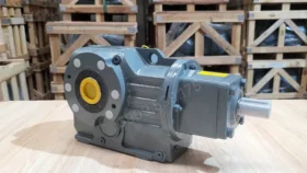
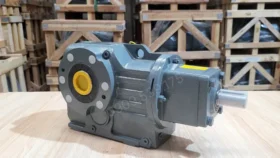
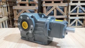
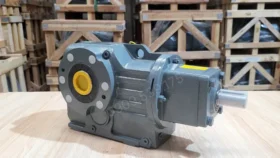
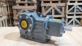
S-Series Helical Worm Gearbox is an essential device in mechanical drive systems, functioning to reduce the rotational speed of an electric motor and increase torque. When combined with an electric motor, this gearbox forms a gear motor-specifically powerful heavy duty gear motor lines that effectively meet transmission demands in heavy industries such as mining, construction, and manufacturing, thanks to their robust structure and superior load-bearing capacity.What is S-Series Helical Worm Gearbox?
Structure of S-Series Helical Worm Gearbox
The internal structure of the S-series is divided into two main transmission stages (2-stage reduction) housed neatly within a specialized cast iron casing:
Gearbox housing: Unlike conventional worm gear series, the S-series housing is cast from high-quality thick grey cast iron, featuring reinforcing ribs running along the body to withstand extreme torsional and centrifugal forces from heavy-duty applications.
1st-stage reduction (helical gear stage): Located right at the input shaft position connected to the motor.
2nd-stage reduction (worm and worm gear stage): Machined as a single piece with the drive shaft from ultra-hard steel, with screw threads precision-ground by CNC machines.
Bearing and oil seal system: The input shaft and worm are supported by symmetrically installed tapered roller bearings to eliminate the extremely high axial forces generated during sliding friction.
Operating Principle of S-Series Helical Worm Gearbox
The S-series gearbox operates on a continuous 2-stage reduction principle to convert high speed into massive pulling force and redirect the drive angle by 90º:
Stage 1: Helical gear reduction: When the electric motor rotates, force transmits directly into the input helical gear pair. This gear pair meshes smoothly to lower the initial speed and slightly increase pulling force (torque).
Stage 2: Right-angle redirection via worm: Force from stage 1 transfers to the ultra-hard steel worm. As the worm rotates, its thread teeth continuously push and slide-mesh with the bronze worm wheel teeth. This mechanism bends the drive direction by exactly 90º.
Output – Massive pulling force release: Due to the specific sliding friction mechanism between steel (worm) and bronze (worm wheel), the rotational speed is slowed down significantly at the output shaft according to the transmission ratio, while releasing a huge torque force to pull ultra-heavy loads.
Classification of S-Series Helical Worm Gearbox
1-Stage S-Series Helical Worm Gearbox
The 1-stage S-Series Helical Worm Gearbox is a speed reducer with a simple structure featuring a single transmission gear pair. Its advantages are compact size and reasonable cost, suitable for applications where transmission ratios do not need to be excessively large. It is commonly used in light industrial machinery and small conveyor systems.
2-Stage S-Series Helical Worm Gearbox
The 2-stage S-Series Helical Worm Gearbox utilizes two transmission gear pairs, allowing it to achieve larger transmission ratios compared to the 1-stage gearbox. This helps increase torque and reduce rotational speed more effectively. It is mainly applied in lifting equipment, industrial mixers, and drive systems requiring high pulling force.1-Stage S-Series Helical Worm Gearbox
Latest S-Series Helical Worm Gearbox price 10/2026 at Thanh Thai Motor
To help our customers easily select the suitable product, Thanh Thai Motor would like to provide the price list for gearboxes, specifically the latest pricing for the S-Series Helical Worm Gearbox. Please refer to the following:
Note: Prices may vary depending on the transmission ratio and mounting type. Please contact us for an accurate quotation.
Advantages of S-Series Helical Worm Gearbox
High load-bearing capacity, durable operation in harsh environments.
High transmission efficiency, energy-saving.
Compact design, easy installation and maintenance.
Diverse transmission ratios to meet various requirements.
Smooth operation with low noise.
Applications of S-Series Helical Worm Gearbox
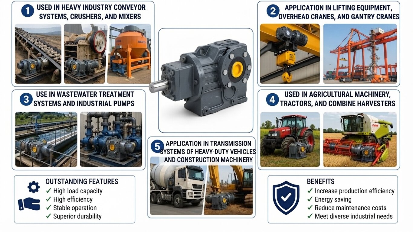
Used in conveyor systems, crushers, and mixers in heavy industries.
Applied in lifting equipment, overhead cranes, and gantry cranes.
Used in wastewater treatment systems and industrial pumps.
Used in agricultural machinery, tractors, and harvesters.
Applied in drive systems of motor vehicles and construction machinery.
S-Series Helical Worm Gearbox Applications
Important Considerations When Buying S-Series Helical Worm Gearbox
Transmission efficiency varies with the transmission ratio: Due to the worm and worm wheel structure in the second reduction stage, the efficiency of the S-series (from 70% to 90%) is lower than that of the K-series bevel gearboxes.
Check self-locking capability: Unlike conventional worm gearboxes, the S-series features a front-assisted helical gear stage, so its self-locking capability is significantly reduced. Even with a large transmission ratio, the S-series gearbox may still experience slight load slippage under heavy pressure. If used for lifting applications or inclined conveyors, it is mandatory to choose a combination with a brake motor.
Accurately determine the output shaft type: The S-series has a diverse right-angle output shaft design to match machine structures:
S-Series: Solid shaft (smooth shaft with keyway).
SA-Series: Hollow shaft (keyed hollow shaft).
SAF / SF Series: Flanged connection (hollow or solid shaft).
SAZ-Series: Small flange hollow shaft (direct mounting to machine wall).
Choose the correct shaft direction and mounting position: Due to its specific mechanical structure, the mounting position (M1 to M6) directly determines the location of the breather plug and lubricating oil level. If you purchase a horizontal design (M1) but install it vertically (M4) without altering the seal structure and oil volume, the top bearings will run dry and seize up after just a few days of operation.
Frequently Asked Questions
Why does the S-series gearbox withstand centrifugal loads and operate more smoothly than the R-series helical gearboxes?
Thanks to the unique combination of helical gears and worms. The meshing mechanism of the worm involves continuous translational sliding friction, completely eliminating mechanical impact noise, providing absolute smooth operation, and absorbing vibration impulse forces from loads extremely well. Additionally, the cast iron housing stage of the S-series is cast very thick to withstand high centrifugal forces from sprocket chains.
When must the oil be changed for the first time in the S-series, and why does this series generate higher heat than the K-series?
The S-series generates higher heat than the K-series because the sliding friction mechanism between the steel worm and bronze worm wheel in the second stage releases significant heat. Upon initial operation, the gear stage will heat up quickly during the first 50 – 100 running-in hours. Customers are required to change the oil for the first time after 500 operating hours, and periodically every subsequent 3000 hours using industrial extreme-pressure gear oil ISO VG 320 or 460 to protect the bronze teeth.
How to handle the shaft backlash phenomenon at the output of the S-series, and what backlash level is safe?
Due to the worm gear tooth structure requiring mechanical clearance for thermal expansion and lubricating oil film retention, the output shaft of the S-series always has a manual backlash of 0.3º to 1º. This is normal. If the backlash increases excessively after several years of use, it means the bronze gear has worn deeply. You will need to disassemble the machine to replace the new bronze worm wheel or re-shim the bearing housings of the worm to tightly press it back.