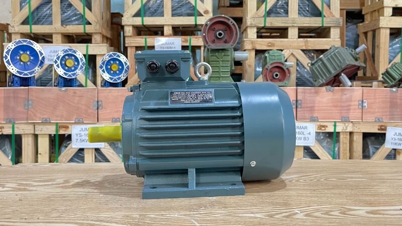
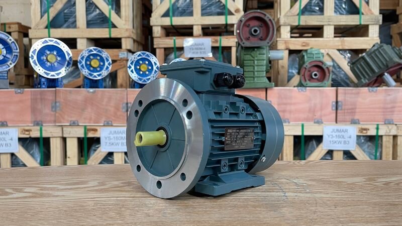
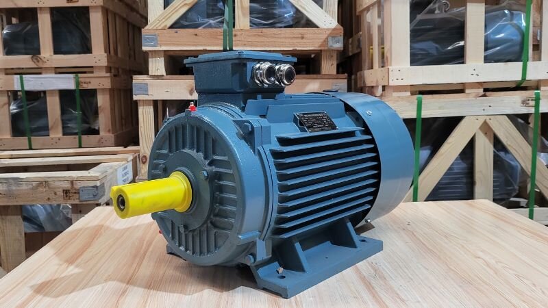
3-Phase Electric Motors are electric motors that use a 3-phase power supply to operate, capable of generating high power, stable operation, and energy savings. With high durability and superior working performance, this product line is commonly used in factories, production workshops, industrial pump systems, conveyors, crushers, presses, etc. Thành Thái Motor is a supplier offering a diverse range of genuine, high-quality 3-Phase Electric Motors to meet all industrial needs.What are 3-Phase Electric Motors?
Detailed structure of 3-phase electric motors
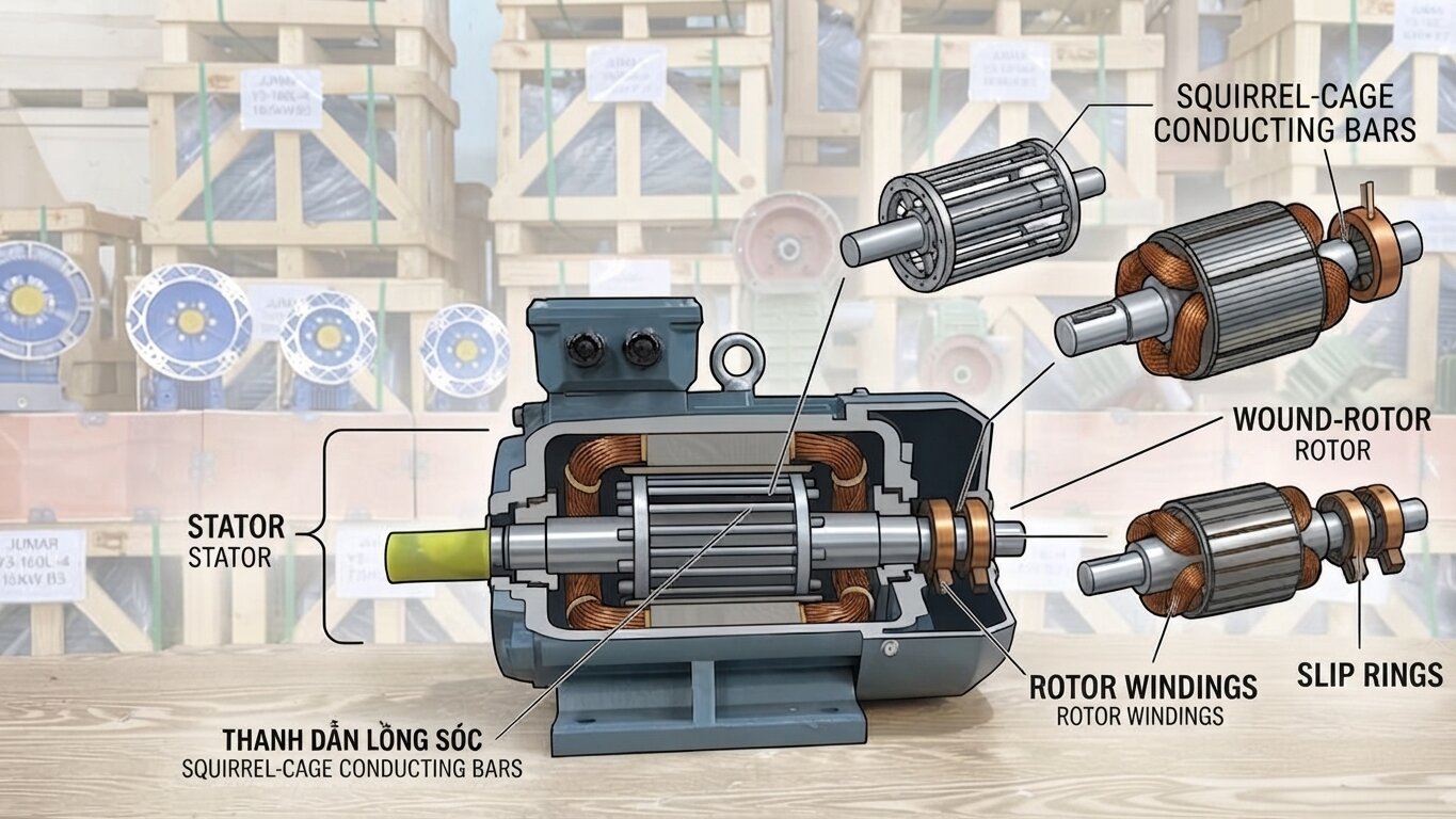
To better understand how Three-Phase Electric Motors work, we need to learn about their structure. A typical 3-phase electric motor consists of two main components: stator and rotor.
Stator
The stator is the stationary part of the 3-phase electric motor. It consists of a cylindrical steel core made of stacked electrical steel laminations. On the inner surface of the steel core, there are slots to place the 3-phase windings. These coils are connected to a 3-phase power supply and generate a rotating magnetic field when current passes through.The quality of the stator material directly affects the performance and lifespan of the electric motor. Thành Thái Motor always selects high-grade electrical steel to ensure the stator operates stably and durably under all conditions.
Rotor
The rotor is the rotating part of the 3-phase motor. There are two common types of rotors: squirrel-cage rotor and wound rotor.
Squirrel-cage rotor
The squirrel-cage rotor is the simplest and most common type of rotor. It consists of a cylindrical steel core with copper or aluminum conductor bars placed in the slots. These conductor bars are short-circuited at both ends by short-circuit rings, forming a structure resembling a squirrel cage. The squirrel-cage rotor has the advantages of simple construction, low cost, and low maintenance.
Wound rotor
The wound rotor has a more complex structure than the squirrel-cage rotor. It consists of a cylindrical steel core with windings placed in the slots. The ends of these windings are connected to slip rings on the rotor shaft. Through carbon brushes, external resistors can be connected to the rotor circuit to adjust the speed and starting torque of the 3-phase electric motor.Detailed structure of 3-phase electric motors
Operating principle of 3-phase electric motors
The operating principle of 3-phase electric motors is based on electromagnetic induction. When a 3-phase alternating current is supplied to the stator windings, it creates a rotating magnetic field. This magnetic field sweeps across the conductors or windings on the rotor, generating an induced voltage. This voltage creates a current in the rotor, and this current interacts with the rotating magnetic field, creating an electromagnetic force that causes the rotor to rotate.The rotation speed of the magnetic field (synchronous speed) is determined by the frequency of the power supply and the number of poles of the electric motor. The actual speed of the rotor is always slightly less than the synchronous speed, so 3-phase electric motors are also known as asynchronous electric motors.
Classification of 3-phase electric motors
Classification by power rating
3-phase electric motors under 3.7kW: These are small motors, commonly used in light industrial machinery systems, industrial fans, water pumps, saws, etc. The advantages are energy saving, easy installation, and smooth operation.3-phase electric motors under 3.7kW3-phase electric motors over 3.7kW: This is a group of high-power motors, suitable for production lines, conveyor systems, concrete batching plants, crushers, etc. This line has high durability, strong performance, high efficiency for heavy loads, and continuous operation.3-phase electric motors over 3.7kW
Classification by product type
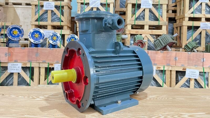
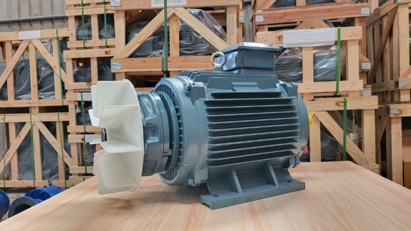
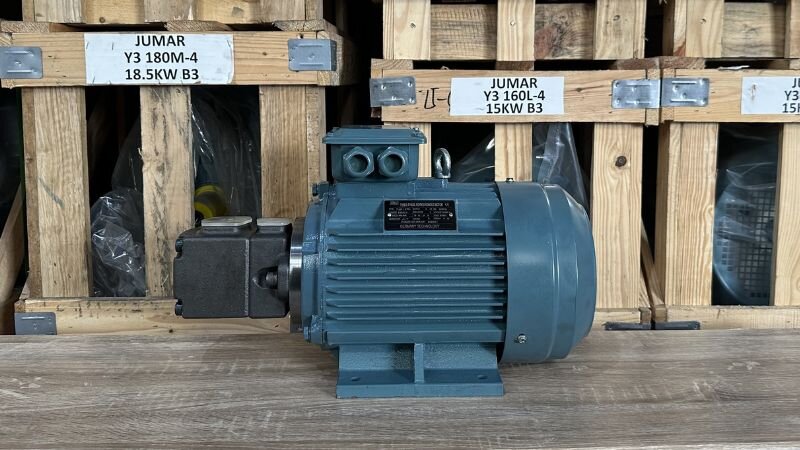
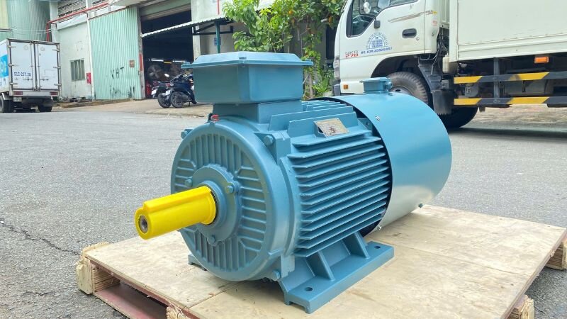
Explosion-proof motor: This is a motor specially designed for use in environments with flammable gases such as coal mines, chemical plants, petroleum warehouses, etc. Explosion-proof motors ensure maximum safety for personnel and equipment when operating in hazardous conditions.3-phase explosion-proof motorBrake Motor:Brake motors are integrated with an electromagnetic brake to help the machine stop quickly when necessary, increasing safety and control capability. This type is applied in cutting machines, lifting systems, overhead cranes, industrial elevators, etc.3-phase brake motorHydraulic Pump: This is a perfect combination of a high-efficiency 3-phase electric motor and a specialized hydraulic pump head. It is applied in hydraulic presses, industrial lifting systems, press brakes, or automated production lines requiring powerful and durable operation.3-phase hydraulic pumpInverter Duty Motor: This is a special motor designed to withstand continuous frequency changes without causing winding heating or energy loss. This is the optimal choice for conveyor systems, agitators, or applications requiring precise speed adjustment to optimize production processes and save electricity.3-phase inverter duty motor
3-Phase Electric Motor Prices at Thành Thái Motor
Pricing for 3-phase electric motors at Thành Thái Motor is based on the diversity of power ratings and energy efficiency standards. Selling prices will vary depending on the rotational speed (2-pole, 4-pole, 6-pole) as well as mounting styles such as foot mount (B3), flange mount (B5, B35). Customers can track the detailed price levels for each machine line from standard to high-end right in the summary table below:
Below are important notes when choosing to buy 3-phase electric motors summarized:
Choose the right energy efficiency: Prioritize lines meeting IE2 or IE3 standards to save electricity and reduce heat dissipation during long-term operation.
Determine the exact rotational speed: Choose 2-pole, 4-pole, or 6-pole depending on the pulling force and speed requirements of the machinery.
Select the appropriate mounting style: Carefully check whether the mounting structure is foot mount (B3), flange mount (B5), or a combination of both (B35) to be compatible with the motor mounting position.
Check dust and water protection class: Ensure the motor reaches at least the IP55 standard for safe operation in dusty or humid industrial environments.
Prioritize copper windings and heavy-duty housing materials: Use motors with 100% high heat-resistant copper windings; choose cast iron housings for heavy-load, vibration-resistant applications or aluminum housings for fast heat dissipation.
Match the duty cycle: Determine whether the motor needs continuous running (S1) or intermittent operation to choose the machine line with the corresponding service factor and load-bearing capacity.
To have an overview of 3-phase electric motor products and wiring instructions, amp measurement methods, etc., customers can visit the summary video page of the electric motor video category to view details.
Frequently asked questions
How to properly connect a 3-phase motor to run in Star or Delta configuration?
Connecting in Star or Delta depends on the grid voltage and the specifications written on the motor nameplate (e.g., 220/380V). If the grid voltage is 380V, you must connect in Star (Y) so that the windings can withstand the rated voltage; if incorrectly connected in Delta, the motor will be overvoltage and burn out immediately.Conversely, if the motor states 380/660V, you need to connect in Delta (Δ) to maximize capacity. You can watch our 3-phase electric motor wiring guide video to avoid mistakes.
Why do 3-phase motors get hot quickly and shake violently right after installation?
There are 2 common technical causes: first, phase loss due to loose wire ends or a damaged contactor, causing the current in the remaining phases to spike; second, shaft misalignment between the motor and the equipment. When the shafts are not concentric, the forced force will destroy the bearings and generate extreme heat at the shaft end. We recommend using a clamp meter to check phase balance and a laser alignment tool to adjust concentricity during installation.
How to handle a 3-phase motor with “reverse rotation direction” and is it dangerous?
This phenomenon occurs because the phase sequence of the power supply does not match the winding diagram. The solution is extremely simple: you just need to swap the positions of 2 out of 3 phase wires (for example, swap wires L1 and L2) and the motor will rotate in the opposite direction. However, with loads such as water pumps or air blowers, reverse rotation is very dangerous because it can cause pump impeller detachment or failure to generate flow, leading to motor burnout due to lack of cooling.