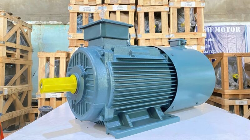
An inverter duty motor is an electric motor specifically designed to operate efficiently with an inverter, allowing flexible and precise control of speed and torque. With superior stepless speed control and energy-saving capabilities, this type of inverter duty motor is an ideal solution for modern industrial applications requiring high flexibility and performance. Thanh Thai Motor specializes in providing high-quality inverter duty motors, helping to optimize production efficiency and operational costs for businesses.
This is a large-capacity motor designed to meet the demanding requirements of heavy industry. Inverter duty motors above 3.7kW are capable of high load tolerance, durable operation, and precise speed control, making them suitable for high-power machinery such as presses, crushers, heavy conveyor systems, industrial pumps, and production lines requiring continuous speed adjustment.
What is an inverter duty motor?
Structure of the Inverter Duty Motor
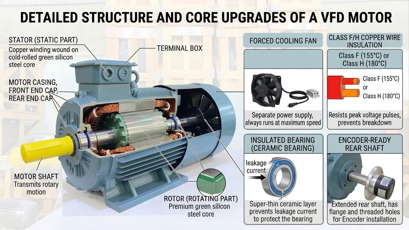
Basically, an inverter duty motor still has all the components of a standard industrial electric motor. Its structure includes:
Stator: Contains copper coils wound on a core made of cold-rolled green silicon steel sheets to reduce magnetic losses.
Rotor: Usually of the squirrel-cage type, also made of high-grade green silicon steel sheets.
Motor housing, front and rear covers: Used to protect and secure internal components.
Motor shaft: Transmits rotational movement outward.
Terminal box: Where electrical wires are connected.
However, what makes an inverter duty motor different and valuable is the following 4 core upgrades, specifically designed to withstand the harsh operating conditions caused by inverters.
Forced cooling fan
Instead of using a shaft-mounted cooling fan like regular motors (which turns slowly when the motor runs slowly, resulting in insufficient cooling), an inverter duty motor is equipped with a forced cooling fan. This is a separate electric fan with its own power source, always running at maximum speed regardless of whether the main motor is spinning fast or slow. This ensures that the motor is always optimally cooled.
Class F or H copper wire insulation
When the frequency decreases, the motor core gets hotter, requiring better insulation. The copper wire of an inverter duty motor uses Class F insulation (withstanding 155°C) or Class H insulation (withstanding 180°C). This high-grade insulation enamel can completely resist voltage spikes from the inverter, preventing insulation breakdown.
Insulated bearings
High-frequency currents from the inverter can generate leakage currents running along the shaft, destroying regular bearings. To solve this problem, an inverter duty motor typically features at least one insulated bearing. This bearing has an ultra-thin ceramic layer that acts as an insulating “wall”, blocking leakage current and protecting the bearing.
Encoder-ready output shaft
To serve precise control applications, the rear shaft of an inverter duty motor is usually designed longer with a flange having pre-drilled threaded holes. This makes attaching an encoder to feed back speed and position signals to the inverter extremely simple and accurate.
Detailed structure of the inverter duty motor
Operating principle of the inverter duty motor
Basically, an inverter duty motor still operates based on the principle of electromagnetic induction like a regular 3-phase motor. The rotating magnetic field generated in the stator induces a current in the rotor, creating an electromagnetic force that makes the rotor spin.
However, the core difference in operating principle is thanks to the structural upgrades (detailed above), giving it the ability to receive continuously changing frequency and voltage power sources from the inverter while still:
Maintaining stable torque over an extremely wide speed range.
Not overheating when operating at low speeds for long periods.
Not damaging internal parts (insulation, bearings) due to the “stresses” caused by the inverter.
What gearboxes can be paired with an inverter duty motor?
An inverter duty motor rarely operates alone; it is typically combined with various gearboxes to form a complete gear motor, accurately meeting speed and torque requirements. Below are the most common combinations on the market.
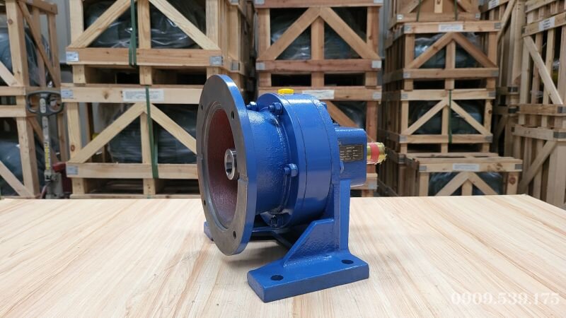
Inverter duty motor paired with a Cycloidal Gearbox
Combining an inverter duty motor with a Cycloidal Gearbox creates a drive unit with exceptional shock and overload capacity. It is ideal for applications such as chemical agitators, building material mixers, or heavy-duty conveyor systems requiring high durability.
Inverter duty motor combined with 4kW 5.5HP Cycloidal Gearbox helps operate durably and handle heavy loads for various industrial applications.
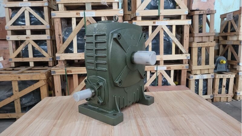
Inverter duty motor paired with a worm gearbox
The solution of pairing an inverter duty motor with a worm gearbox is very popular for applications requiring high self-locking capability. It is often used in hoisting systems, automatic doors, or inclined conveyors to prevent reverse sliding when stopped.
Inverter duty motor paired with a worm gearbox
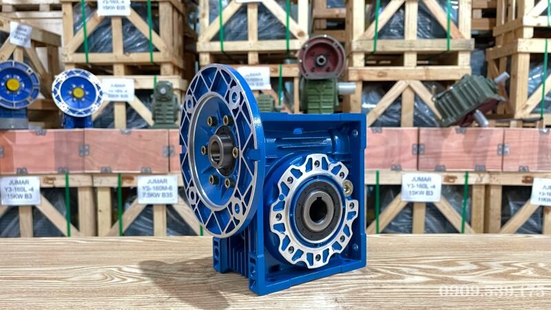
Inverter duty motor paired with an NMRV gearbox
When an inverter duty motor is paired with an NMRV gearbox, featuring a right-angle hollow bore design and lightweight aluminum housing, it becomes an excellent choice for space- and weight-saving applications such as woodworking or textile machinery.
1.5kW 2HP inverter duty motor combined with NMRV 75 gearbox – a compact, durable, and flexible drive assembly for various applications.
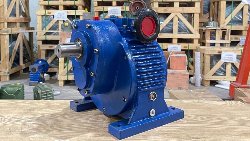
Inverter duty motor paired with a mechanical speed variator
When an application requires both a wide speed control range and a fixed mechanical gear ratio, pairing an inverter duty motor with a mechanical speed variator is a flexible solution. It is commonly found in laboratory machines or production lines requiring speed fine-tuning across multiple levels.
Inverter duty motor paired with a mechanical speed variator
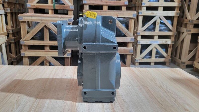
Inverter duty motor paired with an F-Series Parallel Shaft Helical Gearbox
Pairing an inverter duty motor with an F-Series Parallel Shaft Helical Gearbox offers the advantage of a slim, flat design, highly suitable for applications constrained in horizontal installation space, such as agitator systems in narrow tanks and pools.
Inverter duty motor paired with an F-series parallel shaft heavy-duty gearbox
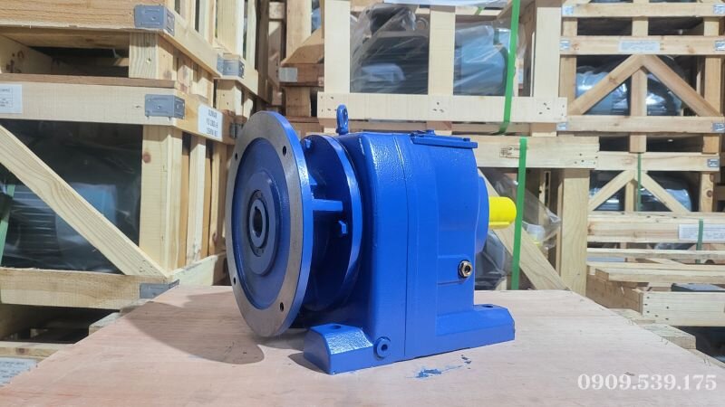
Inverter duty motor paired with an R-Series Inline Helical Gearbox
This is the most common and versatile combination. Pairing an inverter duty motor with an R-Series Inline Helical Gearbox provides very high transmission efficiency, widely applied in almost all industries, from conveyors and bucket elevators to processing machine systems.
5.5kW 7.5HP inverter duty motor combined with an R-series inline helical gearbox – a powerful, durable drive assembly widely used in industry.
Inverter duty motor paired with a K-Series Helical Bevel Gearbox
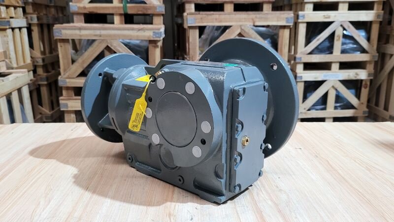
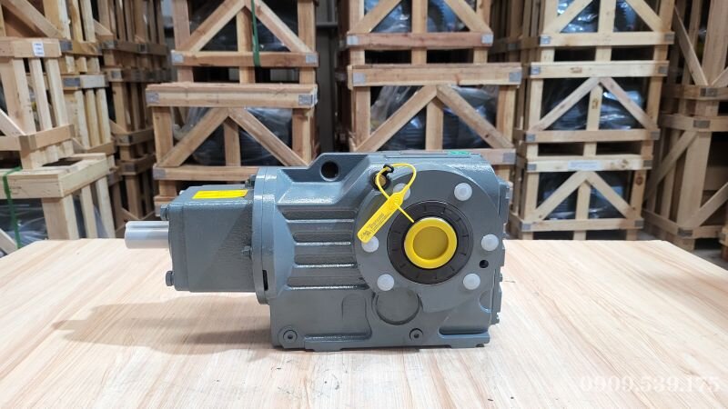
When pairing an inverter duty motor with a K-Series Helical Bevel Gearbox, it creates a high-efficiency drive system with a right-angle output shaft, helping to save space. Common applications include conveyor systems, cargo elevators, agitators, etc.
Inverter duty motor with a K-series right-angle heavy-duty gearbox
Inverter duty motor paired with an S-Series Helical Worm Gearbox
The solution of pairing an inverter duty motor with an S-Series Helical Worm Gearbox combines the advantages of both helical and worm gears, delivering better self-locking capability. It is often used in applications requiring both strong pulling force and load-holding capability when stopped.
7.5kW 10HP inverter duty motor combined with an S-series right-angle helical worm gearbox – optimal solution for heavy loads, inclined conveyors, and lifting mechanisms.
Latest Inverter Duty Motor Prices at Thanh Thai Motor
Below is the latest inverter duty motor prices list, belonging to our comprehensive electric motor pricing catalog. All products are guaranteed to be genuine, with diverse power ratings, suitable for all industrial applications requiring speed control.
How to choose the right inverter duty motor for your needs
Step 1: Analyze load and speed range requirements: Determine what type of load your application belongs to (constant/variable torque) and how wide the speed range is.
Step 2: Select power capacity and technical specifications: Based on the above analysis, choose a motor with the appropriate power, insulation class, and options (insulated bearings, encoder).
Step 3: Recognize an inverter duty motor through design and product nameplate:
Design: The clearest sign is the forced cooling fan (square fan housing) at the rear of the motor.
Product nameplate: Look for symbols such as “Inverter Duty“, “VFD“, “Vector Duty“ or insulation class “INS. CL. F/H“.
Frequently Asked Questions
Why must an inverter duty motor necessarily use an independent forced cooling fan instead of a coaxial fan like regular motors?
Regular motors use a fan attached directly to the shaft. When reducing running speed at low frequencies (below 25Hz), the fan turns very slowly, lacking sufficient airflow for cooling, causing the motor to overheat and burn out its windings. An inverter duty motor thoroughly overcomes this flaw by equipping an independent forced-cooling electric fan (always running at 100% capacity) at the rear, ensuring the motor is always maximally cooled even when running at extremely low speeds or stopping and starting continuously.
What is the phenomenon of “Shaft Current” and how does it destroy bearings in an inverter duty motor?
When the inverter controls the motor using pulse-width modulation (PWM) high-frequency chopping, it creates a parasitic voltage on the motor shaft. When accumulated sufficiently large, this voltage discharges through the oil film of the bearing to ground, causing micro-electric arc discharges. This process pits the raceway surfaces and blackens the lubricating grease, causing the motor to squeal after a short period. To address this, customers need to use insulated bearings or install a grounding carbon brush for the shaft.
Why do the windings of an inverter duty motor have better voltage surge resistance than standard motors?
Harmonics from the inverter create very high voltage surge peaks that easily puncture conventional insulation. Specialized inverter duty motors at Thanh Thai Motor are wound with electromagnetic wire featuring high-grade insulation enamel (usually Class H) and special slot insulation films, withstanding surge voltages up to over 1600V. This helps the motor operate durably with any inverter brand on the market without fear of aging or sudden winding short circuits.