


What is a Hydraulic brake system? Structure and working principle
A Hydraulic brake system is a crucial technology in mechanical devices, particularly in lifting equipment. This system utilizes hydraulic principles to generate efficient and uniform braking force, ensuring safety during the operation of machinery and equipment. This article will delve into the structure, operating principle, and instructions on how to adjust a Hydraulic brake system.
What is a Hydraulic brake system?
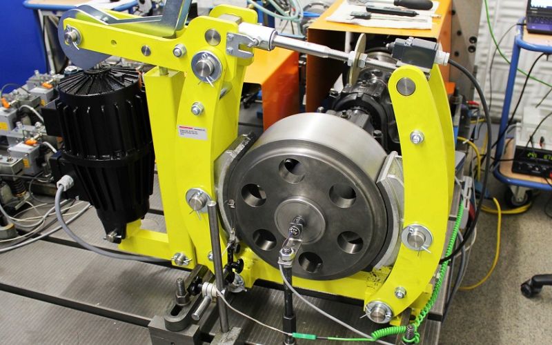
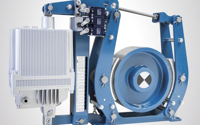
A Hydraulic brake system is an essential component in the transmission mechanism of lifting equipment such as trolleys, winches, hoists, and cranes. This system includes critical parts such as compression springs, brake shoes, and brake thrusters, helping to ensure safety and efficiency during operation.
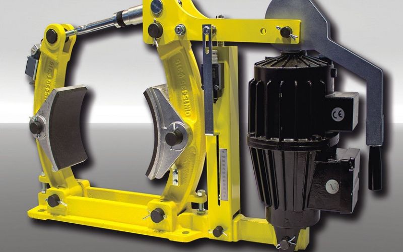
When the braking system is activated, the compression springs create a compressive force acting on the brake shoes to generate the necessary friction to reduce speed or stop the equipment entirely. The brake thruster plays a vital role in containing and regulating the hydraulic oil, ensuring that the braking force is transmitted evenly and effectively.
This lifting equipment often operates in harsh environments and handles heavy loads; therefore, the Hydraulic brake system must function stably and effectively to ensure safety for users and protect the electric motor. The perfect combination of components within the Hydraulic brake system enhances the reliability and durability of the lifting machine.
Structure of a Hydraulic brake system
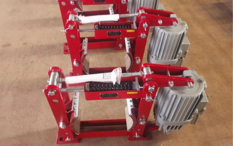
A hydraulic brake consists of the following main components:
- Compression spring system: Has the ability to adjust the clamping force, helping to increase braking torque as required.
- Brake shoes: Combined with brake linings, these can be replaced when the linings are worn. The lining diameter ranges from 100mm to 800mm.
- Brake thruster: This component houses the hydraulic oil pump motor, responsible for releasing the brake during operation. The thruster has different duty cycles: continuous, medium, and light. This is the most critical part of the Hydraulic brake system, affecting the operating frequency and durability of the system.
Operating Principle of a Hydraulic brake system
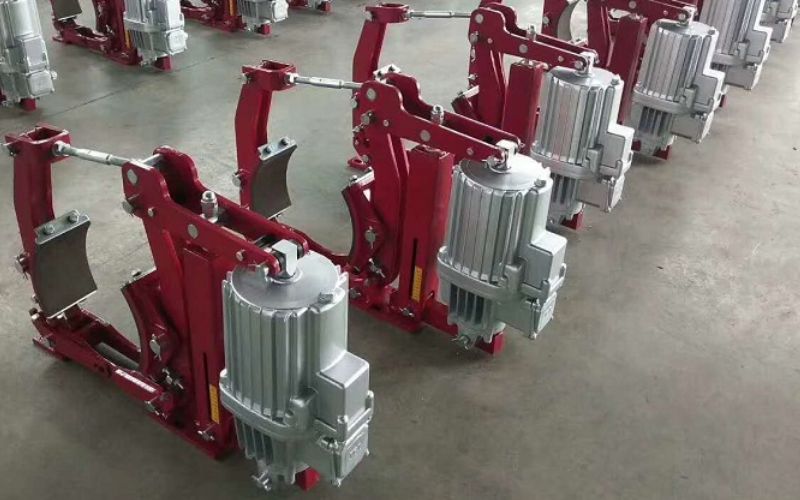
The Hydraulic brake system operates in a normally closed state, with the brake shoes pressed tightly against the brake drum by the force of the spring system. Braking torque varies depending on each type of brake, so selecting the appropriate Hydraulic brake system for the speed and load of each lifting mechanism is very important.
The brake thruster operates in parallel with the main motor (the lifting motor). When power is supplied to the lifting mechanism, the hydraulic pump motor inside the thruster pushes oil into the system to open the brake, with oil pressure torque ranging from 80N.m to 12,500N.m. To ensure optimal performance, checking the thrust of the hydraulic piston is necessary to ensure it operates powerfully and accurately.
The brake drum, mounted on the main motor shaft, allows the motor to rotate freely when the brake is open. When the power source is cut, the spring force closes the brake shoes, tightly gripping the drum on the motor shaft, helping the motor stop safely. If a lack of oil or leakage in the seals or other parts of the thruster is detected, immediate replacement of the thruster is necessary to maintain the safety and performance of the system.
Instructions for Installing and Adjusting a Hydraulic brake system
Below are the instructions for installing and adjusting a Hydraulic brake system:
Instructions for Installing a Hydraulic brake system
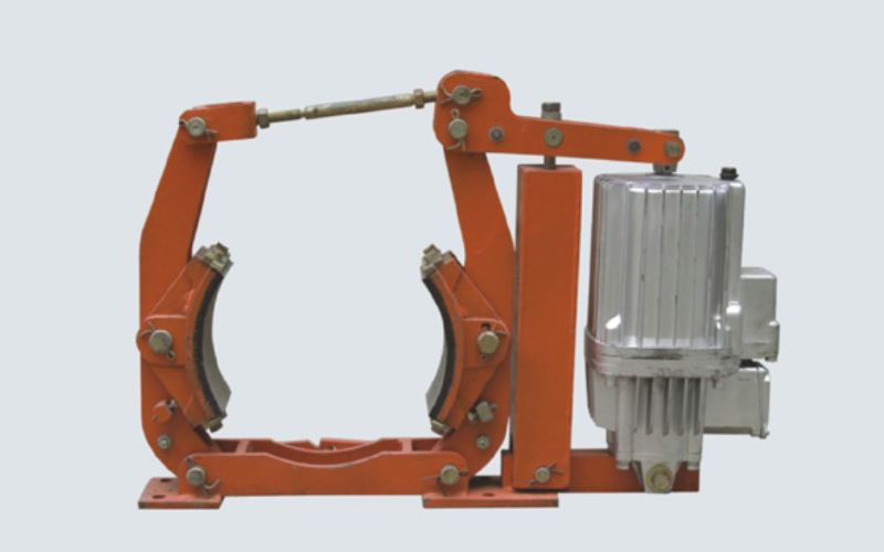
A Hydraulic brake system is often installed at the end of a 1-Phase or 3-phase motor shaft, or on the input shaft of a Gearbox. The drum diameter and braking torque must be adjusted to suit the lifting mechanism to prevent load drifting when lifting objects, especially in the event of an unexpected incident or power failure.
For applications requiring high braking torque, it may be necessary to install multiple hydraulic brakes operating simultaneously or combine them with other types of brakes such as disc brakes, electromagnetic brakes, or motor tail brakes.
When installing the Hydraulic brake system, it must be ensured that when the brake is open, the transmission mechanism operates smoothly, meaning the brake drum can be easily rotated by hand. Furthermore, do not install it misaligned or adjust the brake shoe gaps unevenly, as this can obstruct motor operation and lead to motor burnout.
Instructions for Adjusting a Hydraulic brake system
Below are the steps to adjust a Hydraulic brake system:
Step 1: Loosen the springs and keep the brake in the closed state
- Loosen the entire spring section.
- Turn the pull rod to keep the brake in the closed position.
Step 2: Adjust the thruster pushrod base
- Turn the thruster pushrod base to raise it until the stroke reaches the state specified in the Hydraulic brake system diagram.
Step 3: Check and adjust the brake shoes
- Check for brake lining wear. When the lining wears down, its thickness decreases.
- Readjust the brake to its original state.
Step 4: Adjust the braking torque
- Loosen nut number 6 clamping the head of the pull rod.
- Turn nut number 7 so that the spring reaches the standard assembly length according to the brake specifications.
- After adjusting, tighten both nut number 6 and number 7.
Step 5: Fine-tune the retracting distance of the brake shoes
- When the brake shoes are open, use the adjustment screws to ensure the opening distance on both sides is equal.
- Tighten if there are equalizing link plates.
Step 6: Turn screw number 2
- When turning screw number 2, only turn it enough for the brake and brake shoes to be in the correct position.
- Performing these steps correctly will help ensure the braking system operates stably and safely.
Notes when using a Hydraulic brake system
A Hydraulic brake system is a critical component; to ensure safety and extend the life of the equipment, some points should be noted:
- Always check the condition of the Hydraulic brake system, especially the contact area of the brake shoes. Ensure there are no leaks in the pipes.
- Replace the brake linings if signs of uneven gaps, wear, or cracks are detected. This helps ensure optimal braking performance and safety.
- Evaluate the wear of the pin shafts and center shafts. If the wear exceeds 6% or the ovality reaches a threshold of 0.8mm, they should be replaced to avoid incidents during operation.
- Ensure the environment around the Hydraulic brake system is free from explosive or corrosive substances. The temperature should not exceed 55 degrees Celsius to avoid damage to the system.
By following these notes, you can maintain the performance and safety of the Hydraulic brake system throughout its usage.
Conclusion
A Hydraulic brake system, with a structure consisting of main parts such as the brake thruster, brake shoes, and compression springs, helps create a powerful and stable braking force. The operating principle is based on transmitting force through fluid, allowing for precise and safe control. Understanding this system clearly will help improve performance and reliability in practical applications.