Stepper Motor Control is the process of supplying sequential electrical pulses to stator windings to create precise angular movement for the rotor. This process is not just about making the motor rotate, but also involves precisely controlling the position, speed, and rotation angle as required by the application. By changing the frequency, sequence, and number of pulses supplied to the driver, users can achieve smooth motion and positioning with extremely low error, widely applied in CNC machines, 3D printers, and industrial robots.
Key points to master regarding Stepper Motor Control:
Core Principle: Control is based on supplying electrical pulses in a specific sequence. Each pulse corresponds to one angular step of the motor.
Main Components: A pulse source (microcontroller, PLC) and a driver are always needed to amplify and distribute current to the windings.
Common Modes: These include Full-step, Half-step, and Micro-stepping, each with its own advantages and disadvantages regarding torque and smoothness.
Deciding Factors: Selecting a driver compatible with the rated current and rated voltage of the motor is the most important factor for stable and durable system operation.
Understanding these principles will help you easily approach the more detailed techniques in the article below.
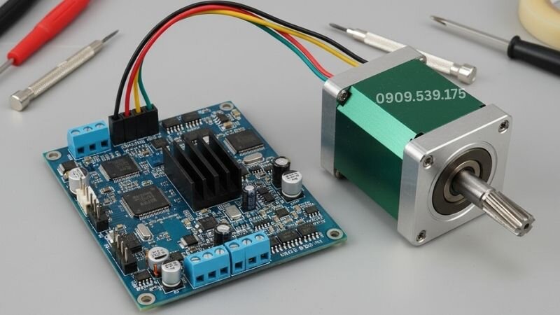
Stepper motor control circuit.
How does the principle of Stepper Motor Control work?
In essence, Stepper Motor Control is the art of switching current on and off in the windings according to a pre-calculated sequence. Understanding this foundation helps you master the equipment effectively.
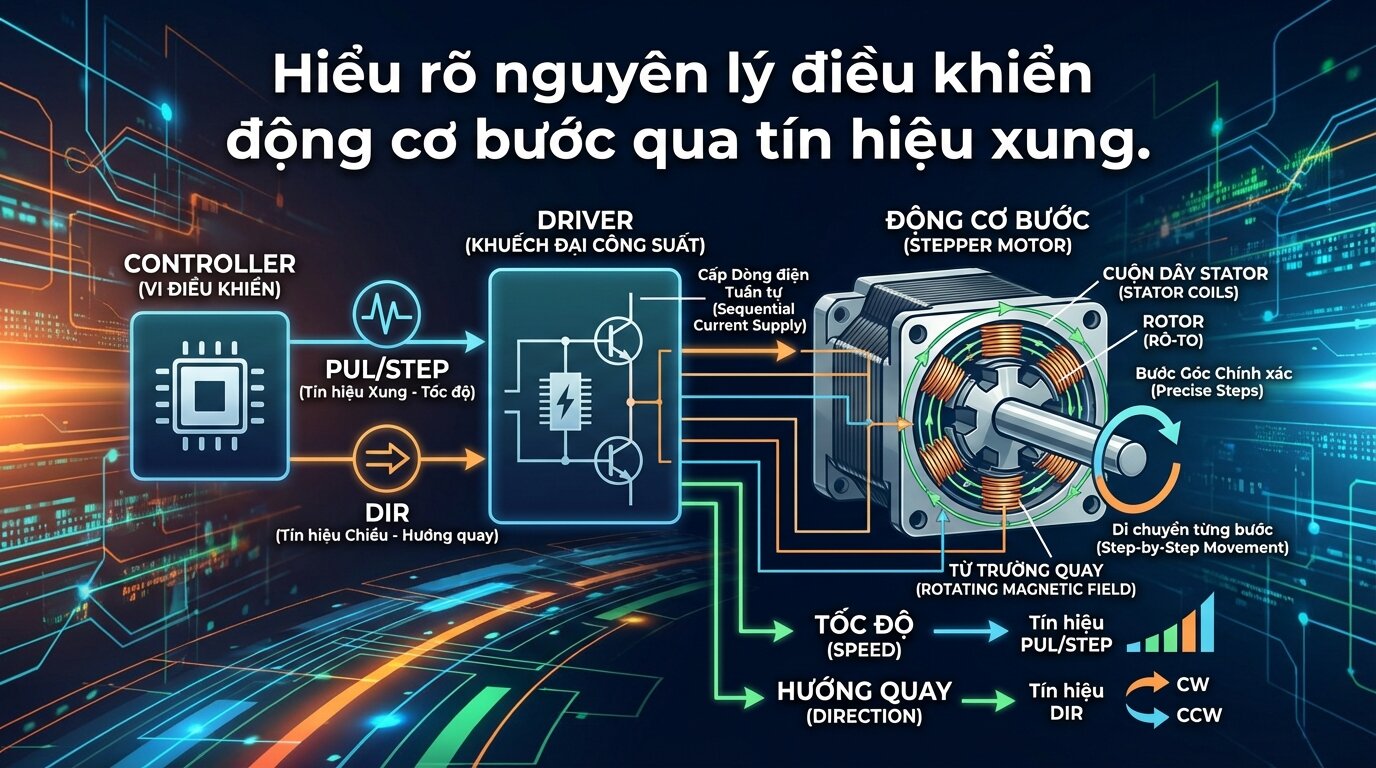
Understanding the principle of stepper motor control via pulse signals.
Role of Electrical Pulses (Pulse/Step) and Direction (DIR)
These two signals are the most basic commands that the controller receives. They determine every movement of the motor.
The PUL/STEP pulse determines the rotation speed. The higher the pulse frequency, the faster the motor rotates and vice versa. Each pulse is a “take one step” command.
The DIR pulse determines the rotation direction of the stepper motor. One logic level (high or low) dictates clockwise rotation, while the other logic level dictates counter-clockwise rotation.
Why is a Driver needed?
Microcontrollers or PLCs can only output logic signals with very small currents, which are not strong enough to rotate the motor. The driver acts as a power amplifier.
It receives weak pulse signals and transforms them into strong currents sufficient to power the motor windings. It can be said that the driver is an indispensable power bridge between the controlling “brain” and the executing “muscle.”
Principle of Sequential Power Supply to Stator Windings
This is the core of the Stepper Motor Control principle. The driver sequentially supplies current to the phase windings (usually labeled A, B, A-, B-) to create a rotating magnetic field.
This magnetic field “pulls” the rotor, which is a permanent magnet, to rotate in discrete angular steps, creating the precise movement we desire.
Comparison of Popular Stepper Motor Control Methods
Each Stepper Motor Control method offers its own advantages and disadvantages regarding smoothness, torque, and resolution. Choosing the right method will optimize performance for your application.
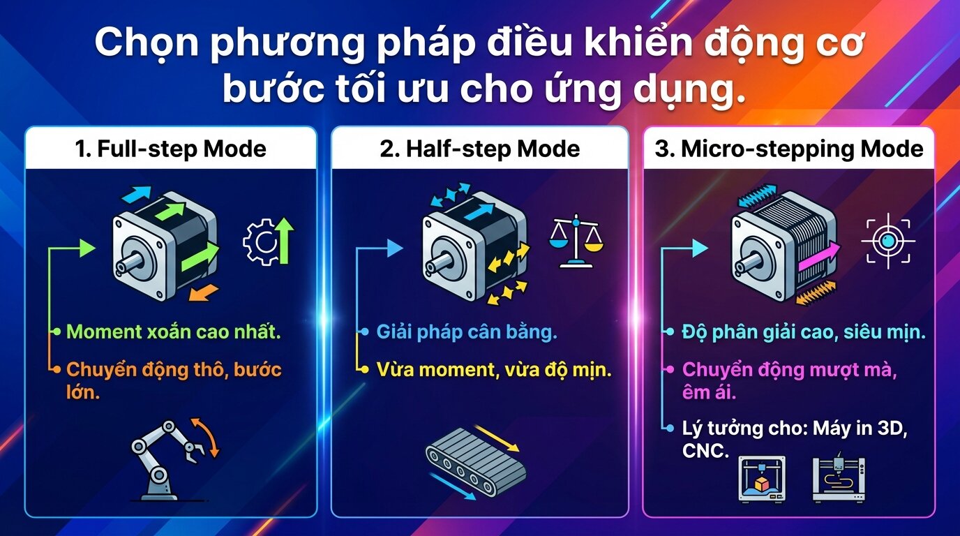
Choosing the optimal stepper motor control method for the application.
Criteria
Full-step
Half-step
Micro-stepping
Principle
Powering 2 phases simultaneously
Alternating between 1 phase and 2 phases
Supplying sinusoidal current to phases
Resolution
Low (e.g., 1.8°/step)
Medium (e.g., 0.9°/step)
Very high (e.g., 1/16, 1/32 step)
Smoothness
Low, vibrates at slow speeds
Relatively smooth
Very smooth, almost no vibration
Torque
Highest
Approx. 30% lower than Full-step
Lower at high speeds
Application
When high torque is needed, high precision not required
General applications, balancing speed and smoothness
3D printers, CNC, medical devices requiring precision and quietness
The table above summarizes basic Stepper Motor Control modes to give you an overview for selection.
Guide to Selecting a Suitable Stepper Motor Control Unit (Driver)
Choosing the right driver is just as important as choosing the motor. An unsuitable Stepper Motor Control unit can cause overheating, step loss, or even damage the entire system.
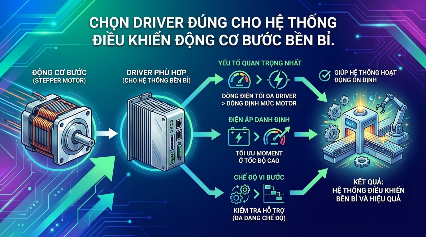
Choosing the right driver for a durable stepper motor control system.
Determine the Rated Current (Amps) of the Motor
This is the golden rule. Always choose a driver with a maximum output current (peak current) higher than or equal to the rated current marked on the motor body.
Most drivers have DIP switches for you to set the appropriate operating current. This helps the motor and driver operate within safe limits.
Pay Attention to the Rated Voltage
The voltage supplied to the driver directly affects performance at high speeds. A higher voltage level helps the motor maintain better torque when rotating fast, counteracting torque drop-off.
However, you should not exceed the voltage limits allowed by the driver.
Select the Desired Micro-stepping Mode
Check the driver specifications to ensure it supports the micro-stepping modes your application requires. Common modes are 1/8, 1/16, 1/32, 1/64…
The higher the micro-stepping mode, the smoother the movement, but it may reduce torque in certain speed ranges.
Advice from Thanh Thai Motor engineers: Always choose a control unit with a maximum current 20-30% higher than the rated current of the motor. This helps the driver run cooler, more stably, and increases the lifespan of the entire system, avoiding overheating or step loss under heavy loads.
If you are still hesitant in your selection, do not hesitate to contact the engineering team at Thanh Thai Motor via Hotline: 0909.539.175 for free consultation and to find the most optimal solution.
How to Accurately Control Position, Speed, and Rotation Angle?
Mastering motion parameters is the ultimate goal of Stepper Motor Control methods. We can control them through programming pulse signals.
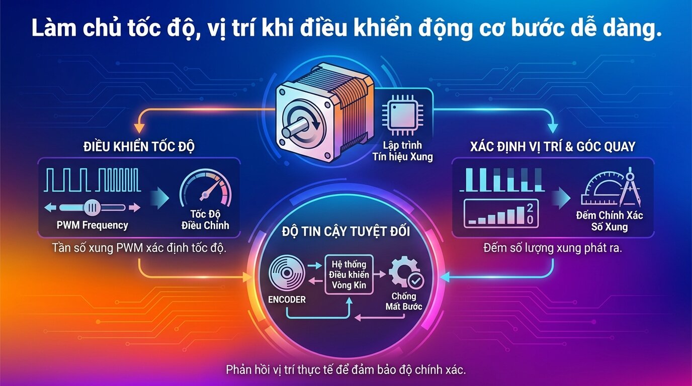
Mastering speed and position during stepper motor control easily.
Speed Control Using PWM Pulse Frequency
The rotation speed of a stepper motor is directly proportional to the pulse frequency supplied to the PUL/STEP pin. If you want the motor to rotate faster, simply increase the pulse frequency.
A basic calculation formula helps you determine this parameter:
Speed (RPM) = [Pulse Frequency (Hz) * 60] / [Steps per Revolution * Micro-stepping Mode]
Pulse Frequency (Hz): Number of PWM pulses supplied per second.
Steps per Revolution: Motor specification (commonly 200).
Micro-stepping Mode: The denominator of the mode. For example, for 1/8 micro-stepping, this value is 8.
Controlling stepper motor speed is essentially controlling the frequency of this signal.
Control Rotation Angle and Position by Counting Pulses
The principle is very simple: to move the motor to a specific position, you only need to supply it with a precise number of pulses.
Example: For a motor with a step angle of 1.8 degrees/step, to rotate a stepper motor by an angle of 90 degrees, you need to supply: 90 / 1.8 = 50 pulses. Positioning a stepper motor follows the same principle.
When to Use Closed-loop Control with an Encoder?
Standard systems operate in open-loop mode, meaning the controller only issues commands without knowing if the motor executed them correctly. This can lead to step loss during overload.
To overcome this, we use closed-loop control. An encoder is attached to the motor shaft to read the actual position and send a feedback signal back to the controller, helping the system automatically compensate for errors and ensuring steps are never lost.
Wiring Diagram and Basic Stepper Motor Control Circuit Installation
Correct physical connection is the first step for the system to operate. Always refer to the driver and motor datasheet for the correct stepper motor wiring diagram.
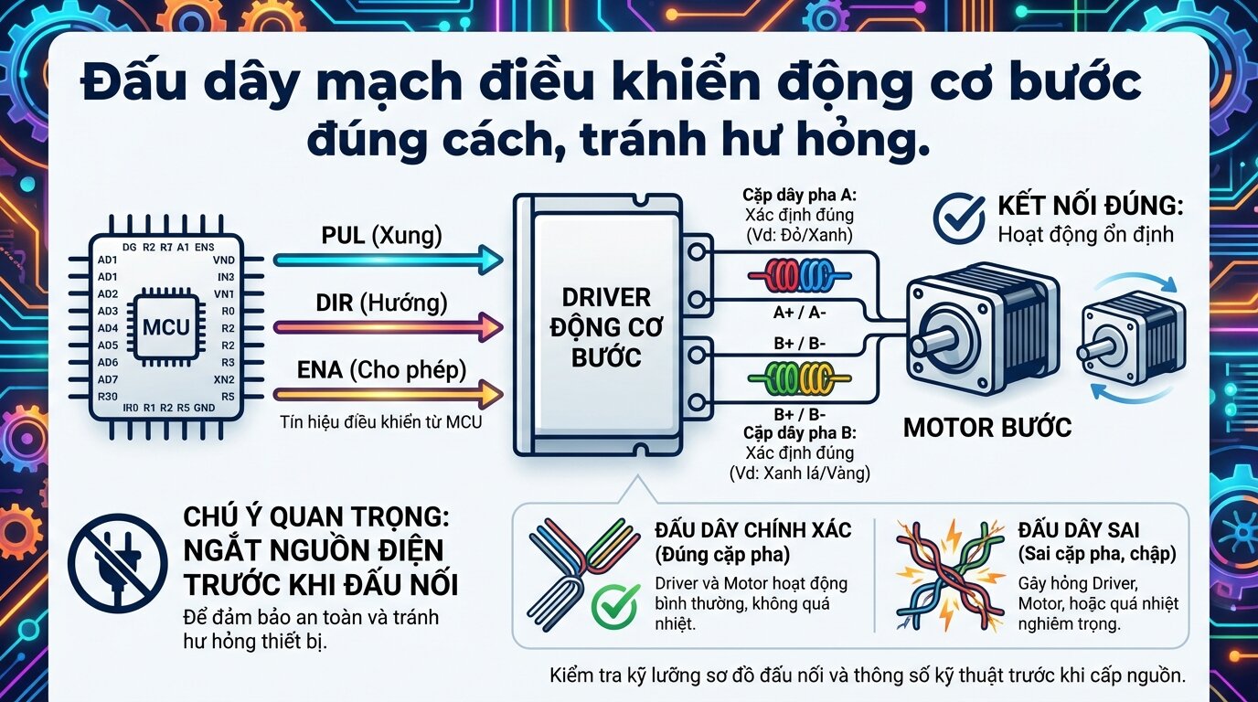
Wiring a stepper motor control circuit correctly to avoid damage.
Connection Diagram between Microcontroller (Arduino/PLC) and Driver
Control signal connection is usually very simple. You only need to connect the pulse output pins of the microcontroller to the corresponding signal input pins on the driver.
Basic signal pins include: PUL+, PUL- (for step pulses), DIR+, DIR- (for direction pulses), and ENA+, ENA- (for enable).
How to Wire from Driver to 4-wire, 6-wire, and 8-wire Stepper Motors
Identifying the correct phase winding pairs is extremely important. You can use a VOM multimeter in resistance mode to find pairs of wires that are continuous (A+ and A-, B+ and B-).
With 6-wire or 8-wire motors, you have options for series or parallel connection to optimize between torque and speed. Specific diagrams for a stepper circuit are always included in the product documentation.
Safety Warning: Always disconnect all power sources before performing wiring or changing wire connections. Plugging/unplugging motor wires while the driver is powered can cause immediate damage to the Stepper Motor Control unit.
Conclusion
Mastering Stepper Motor Control principles is the key to unlocking the full potential of this high-precision motor type. From understanding the nature of electrical pulses and selecting the right Stepper Motor Control unit compatible with technical specifications, to applying control methods from basic to advanced, all contribute to creating a stable and efficient motion system.
Every application will have unique requirements, and experimenting with and fine-tuning parameters such as current, acceleration, and micro-stepping modes is an indispensable step to achieve the best results.
Thanh Thai Motor not only provides quality motors and control units but is also ready to accompany you as a technical consulting expert. If you have any questions or need a specialized solution, contact us immediately.